


Hot Isostatic Pressing Equipment
A hot isostatic pressing system usually consists of five major components: pressure vessel, internal furnace, gas handling, electrical, and auxiliary systems.
Hot isostatic pressing systems currently range in size from 1 to 80 in. (25 to 2000 mm) diameter. The smaller units usually are used for research. It is common practice to design one unit universally for research processes such as: densification of ceramics at 3,600°F (2,000°C), hot isostatic pressing of cemented carbides at 2,700°F (1,500°C), consolidation of superalloy powders at 2,200°F ( 1,200°C) and carbon impregnation at 1,800°F (1,000°C). This can be accomplished with one basic system but with various plug-in furnaces and a versatile control system. Larger size production units are usually designed for handling a specific process but can also accept various plug in furnace types. Standard production equipment for all of the processes listed is available.
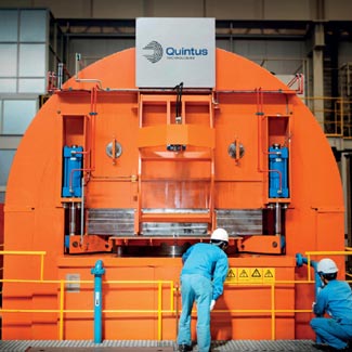
Pressure Vessel
Hot isostatic pressing vessels have either threaded or threadless closures. They consist of a vessel body with threaded top and bottom covers or threadless body and threadless closures with a yoke frame. The pressure vessel in a HIP system contains the high-temperature furnace and retains the high-pressure gas. Utility connections to the furnace typically extend through the bottom cover and require a reliable pressure seal as well as electrical isolation from the vessel. Elastomer O-rings seal the gas in the vessel since the vessel temperature is kept below 480°F (250°C).
The design of any pressure vessel must meet two essential requirements. They are the minimum dimensions based on allowable stress and fatigue life. Reference ASME codes Section VIII, Division 2 and 3 for additional information.
Furnaces
 The hot isostatic pressing furnace, contained within the pressure vessel, provides the heat required either from direct radiation, gas convection, or forced-gas convection. Within the furnace are electrical resistance heating elements and a space for placing the work piece (tooling and components to be HIPed). The pressure vessel is designed as a "cold wall vessel" and is protected by a thermal barrier that prevents hot gas penetration to the inside of the vessel wall. Furnaces can be constructed to "plug-in" with the work piece in place. Direct thermocouple attachment takes place outside the vessel.
Radiation furnaces are typically multi-level, multi-zone styles with the heating elements surrounding the work piece. There are two types of radiation furnaces used; the cold load system where the element and work piece start at room temperature and are heated together, or the hot load system where the work piece is preheated outside the vessel then loaded into the hot furnace cavity.
Natural convection furnaces are common for many sizes of HIP units. They work by heating the dense gas in the furnace element area and conveying it to the work piece above by the buoyancy of the hot gas molecules. In this type of furnace, a convection liner creates a path for the gas flow as its energy dissipates to the work piece and as more hot gas molecules move upward from the element. This gas circulation continues until the temperature is equalized throughout the work area.
Forced convection furnaces are also of single or multi-level construction but have a fan to circulate the gas. Heat transfer to the work piece is a function of the full coefficient of heat transfer of the gas. By increasing the gas velocity the final coefficient is increased to provide high heating/cooling rates. The limitations for a system are now only a matter of furnace power for heating and the pressure vessel heat flux capability during cooling.
There are several advantages to using convection furnaces. The work piece is not exposed to direct radiation from heater elements. There is a larger work cavity available for a given vessel diameter. Heating elements are not susceptible to damage by the load/unload process, and construction is much simpler than that for multi-level radiation furnaces.
Many different furnace element materials are available for hot isostatic pressing furnaces. Each element material has characteristics that affect its capability in HIP applications. The three most common element materials are graphite, molybdenum, and nickel/chrome.
Gas Handling
Hot isostatic pressing processing requires an inert gas to apply an equal (iso) force to the part for densification. Most systems use argon as the pressurizing medium.
HIP systems often require pressures to 15,000 psi (103 N/mm2) and sometimes even up to 45,000 psi (N/mm2) depending on the material being processed. Gas pressures can be achieved with a compressor and/or by thermal expansion.
Diaphragm compressors are most common for pressures up to 15,000 psi (103 N/mm2). They are motor driven and have a reciprocating piston that develops oil pressure to deflect the metal diaphragm. Triple diaphragms with leak-detection monitors ensure that oil cannot enter into the gas stream. The diaphragm life is from 200 to 500 hours depending on gas cleanliness and service conditions. A combination of two separate compressors has been used for pressurization and gas reclamation. The primary compressor is rated to 3600 psi (25 N/mm2) and is used to boost the secondary compressor rated to 15,000 psi (103 N/mm2) for increased capacity. The primary compressor can also be used to reclaim 90% of the gas from the vessel, depending on its cleanliness.
Non-lubricated piston compressors are electro/ hydraulically driven single or dual stage and rated to 29,000 psi (200 N/mm2). The drive fluid is segregated from the process gas to avoid contamination. Seal life is about 500 to 1,000 hours, depending on the service conditions.
Liquid pumps are attractive for larger capacity requirements on production systems up to 1,000 N/mm2/hr for 20,000 psi (138 N/mm2) pressures. These compressors are motor-driven reciprocating piston pumps and compress the fluid in the liquid state which is then vaporized before it enters the vessel. The seal life is about 1000 hours depending on the service conditions. One drawback of liquid pumps is their inability to recover the gas. Gas recondensing has not been demonstrated to be cost effective to date.
Gas purity is very important when processing parts such as castings which are susceptible to oxygen, hydrogen, carbon monoxide, carbon dioxide, water vapor, and hydrocarbons contamination. Gas with 99.995% purity (50 PPM total impurities) is acceptable to prevent premature furnace failure but can be harmful to superalloys or titanium which require less than 5 PPM total impurities. The gas can be purified with gas dialysis equipment or by gettering in the HIP furnace. On-line gas analysis is a must when processing surface-exposed parts.
Controls
The control system for a hot isostatic pressing unit is the subsystem that links the vessel/furnace, gas handling, and auxiliaries into a functioning research or production tool. Computer control ensures repeatability of these parameters to maintain consistency of operation.
HIP equipment requirements dictate that a versatile control system is necessary. Research and laboratory scale equipment is available with furnace styles that vary widely in construction and operation. These interchangeable furnaces have different elements and thermocouples operating over a wide range of temperatures. The mini- and micro-computer control allows for the changes via programming and software. This provides operation throughout the whole range of cycle parameters with accuracy and repeatability.
The heart of the control system is the control panel. Operation is performed by a sequence of events initiated at the control panel by some form of logic. The common logic types available are relay, programmable controller (Level 1), mini- and micro-computer (Level 2), and total computer supervision (Level 3).
Level 1—Relay and programmable controller logic are similar to controls used in many industrial environments. These units typically require continuous operator interface to provide the judgment and initiation to proceed with each step of the HIP cycle.
Level 2—The mini- and micro-computer controls allow for complete automatic control of HIP cycles. The cost of a single microprocessor chip has steadily declined until mini and micro computers are cost competitive with relay logic and programmable controllers.
Level 3—Total computer supervision is provided by a highly sophisticated system that operates HIP production equipment without an operator interface. This system includes load/unload systems with machine robots for materials handling. This system handles every phase of HIP production from the raw material to the finished product.
Auxiliary Systems
A HIP system is supported by a number of important subsystems classified as auxiliaries. These include cooling and vacuum systems, material handling with work piece fixtures and facilities subsystems including exhaust fans, oxygen monitoring equipment, and cranes.
- The cooling system keeps the pressure vessel temperature below its design limits. Closed-loop cooling is used with treated water to prevent corrosion of low alloy steel pressure vessels. Since cooling is essential for energy removal from the vessel, the system is provided with temperature and flow sensors.
- The vacuum system provides a means of removing the atmospheric contaminants from the furnace/vessel. Commonly a mechanical pump with a Roots-type blower is used for handling high flow rates at low pressure. Isolation is provided by a high-capacity high-pressure vacuum valve. System interlocks ensure safety and prevent exposure of the vacuum components to high pressure.
- Material handling can be integrated into the furnace design. The furnace can be loaded outside the vessel with the thermal barrier placed over the work piece and locked in place. The furnace and work piece are then lowered into the vessel as a single module. Alternatively, the thermal barrier can be removed and the work piece lowered into the vessel on a fixture. Either of these methods uses a crane for handling the furnace load.
- Work piece fixturing is determined by the material being processed as well as by the operating temperature. Work piece fixtures for various materials vary but commonly used materials for superalloy billets and castings are materials that maintain strength at high temperatures. Carbon steel has a relatively high melting temperature and is used in some applications. Materials such as nickel/chrome alloys with high creep strength are not prone to severe phase changes. They can be used also for work piece fixtures. For processing tungsten carbide, where high temperatures are required, a purified graphite fixture is used. This 4,000°F (2,200°C) HIP application requires a combination ceramic and graphite fixture.
- Oxygen monitoring equipment is used with inert gases which are heavier than air and do not support life. Strict safety precautions must be followed. It is possible to be asphyxiated in the confined space of a pit or pressure vessel where the air has been displaced by the inert gas. Oxygen monitoring and exhaust equipment are essential for the safety of personnel. The monitoring equipment can be set up to automatically start exhaust fans and give warnings of an oxygen deficiency.