


Case Studies
Case Study 7
Component: Diesel Engine Valve Lifter
Process: HIP
Size: 82.55 mm (3.25 in.) long x 35 mm(1.4 in.)
Weight: 204 g (0.45 lb.)
Alloy: Tungsten Carbide Face and Steel Shaft
Density: 100% at bond surface
Secondary Operations: Grinding on Face Only, Finish Machine Stem
Alternative Process: Furnace Brazing
Annual Production: 400,000
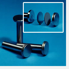
Description:
A HIP-clad valve lifter used in a full range of medium- to heavy-duty truck diesel engines replaced a furnace brazed part, offering a higher-quality bond, a drastic reduction in scrap, and no field failures. The wear face of the valve lifter rides on the camshaft, opening and closing the engine valves. The HIP-clad product consists of a 9% Co-bonded tungsten carbide (WC) face, made from powder and pressed and sintered; a steel sheet metal cap fitted over the WC disk; a copper-alloy foil interlayer; and a steel shaft. The steel cap is electron-beam welded to the steel shaft and then hot isostatically pressed to provide a very strong 100% bond. The HIPing takes place at 1,010°C (1,850°F) at a pressure of 100 MPa (15,000 psi).
The tungsten carbide face has a density of 14.52–14.72 g/cm3, a hardness of 90.8 ± 5 HRA, and a transverse rupture strength of 2,450 MPa minimum (355,000 psi).
Secondary operations are limited to grinding the face to remove the sheet metal cap and exposing the high-wear-resistant tungsten carbide face. The steel cap is left on the edge surface to prevent damage during assembly.
Case Study 12
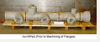
Component: Offshore Oil and Gas Manifold
Process: HIP
Alloy: Duplex stainless steel UNS S31803
Size: Manifold section—2.5 m (8.2 ft.) section length welded to a 12 m hollow component
Tubular portion diameter—0.355 m (14 in.)
Weight: 6.6 short tons
Tensile Strength: 750 N/mm2 (at RT)
Yield Strength: 540 N/mm2 (at RT)
Impact Toughness: > 100 J at -46°C
Elongation: 35%
Apparent Hardness (all parts): 235 HRB
Density (all parts): 7.85 g/cm3 (0.283 lb./in.3)
Heat Treatment: Water Quench
Secondary Operations: Machining to prepare for weld bevel on circumferential welds on header OD and sealing areas of connecting flanges.
Alternative Process: Forging and machining + extensive welding
Annual Production: Custom fabrication
 Description:
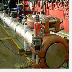
The manifold components are fabricated using formed sheet elements designed and welded in a configuration necessary to meet geometrical design of the finished product. According to design codes for pressure vessels, there are reinforced areas required at the nozzle area of a header. With hot isostatic pressing (HIP) technology it is possible to reinforce the outlet by making the wall thickness of the outlet on the manifold section thicker than the run pipe. To produce an outlet by using conventional wrought extruded techniques, a thicker run pipe is necessary. In contrast, the HIP techniques require less material and lighter construction. It is also possible to adjust the branch height and integrate the flange without critical welding, thus reducing necessary welding and X-ray weld testing.
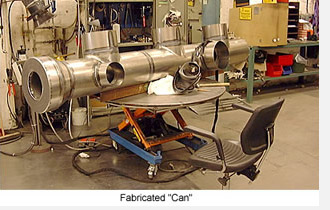
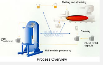
Depending on series length and the shape of the components, different ways of manufacturing the can are used. Flanges are manufactured from sheet materials formed by spin forming and then welded to produce the "can" to contain the atomized, pre-alloyed metal powder. Most manufacturers have developed proprietary design software to optimize and predict necessary initial dimensions necessary to achieve final near-net shape.
Further advantages in employing the HIP process in this and similar applications is isotropic material properties, lower-weight potential, reduced critical welding, 100% ultrasonic inspectability, more design freedom, and much shorter delivery time.